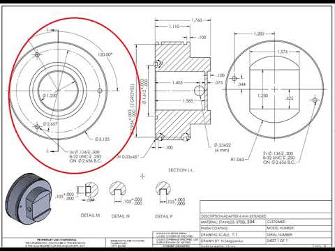
Deciphering the Blueprint: An In-Depth Guide on How to Read Engineering Drawings

In the intricate world of engineering, the ability to read and interpret technical drawings is a fundamental skill. Engineering drawings, also known as blueprints or technical drawings, serve as the visual language of the industry, conveying precise information about the design, dimensions, and specifications of a project. This comprehensive guide aims to unravel the complexities of engineering drawings, providing a step-by-step exploration of the key elements, symbols, and techniques involved in reading these crucial documents.
Understanding the Basics of Engineering Drawings
1. Types of Engineering Drawings:
- Orthographic Drawings: These represent a three-dimensional object in two dimensions, usually through a series of multiple views (front, top, side).
- Isometric Drawings: This type of drawing presents a 3D object in a single view, allowing for a more intuitive understanding of the spatial relationships between components.
- Sectional Drawings: When an object needs to be viewed as if cut by a plane, sectional drawings provide a detailed view of the internal structure.
- Pictorial Drawings: These include isometric, oblique, and perspective drawings, offering a more realistic representation of the object.
2. Standardization and Symbols:
- Engineering drawings adhere to specific standards, such as those set by the American National Standards Institute (ANSI) or the International Organization for Standardization (ISO).
- Standard symbols, line types, and abbreviations are used universally to ensure clarity and consistency across drawings.
Essential Elements of Engineering Drawings
1. Title Block:
- Located in the lower right or lower left corner, the title block contains essential information about the drawing, such as the title, part number, revision history, and the name of the drafter.
2. Drawing Number:
- Each drawing is assigned a unique identification number, facilitating easy referencing and organization in large projects.
3. Views:
- Different views of the object, including front, top, side, and sectional views, provide a comprehensive understanding of its geometry.
4. Dimensions:
- Dimensions are crucial to understanding the size and proportions of the object. They are typically presented in numerical values with units.
5. Notes and Annotations:
- Clarifying information, material specifications, and additional details are often provided through notes and annotations on the drawing.
6. Symbols and Legend:
- Symbols, such as geometric tolerancing symbols or welding symbols, convey specific information about manufacturing processes and requirements.
7. Bill of Materials (BOM):
- A detailed list of all components, materials, and quantities needed for the project is often included in the drawing or in a separate BOM section.
Step-by-Step Guide to Reading Engineering Drawings
Step 1: Understand the Drawing Format and Scale:
- Familiarize yourself with the title block to gather information about the drawing. Identify the drawing scale to interpret dimensions accurately.
Step 2: Analyze Views:
- Examine different views of the object to gain a comprehensive understanding of its shape and structure. Pay attention to hidden lines and section views.
Step 3: Interpret Dimensions:
- Read dimensions carefully, considering the units of measurement. Note key dimensions that define the critical features of the object.
Step 4: Identify Symbols and Annotations:
- Look for symbols and annotations that provide additional information about tolerances, surface finishes, or specific manufacturing processes.
Step 5: Check for Revisions:
- If the drawing has revision history, check for any updates or changes. Ensure you are working with the latest version.
Step 6: Refer to the Bill of Materials:
- Cross-reference the bill of materials to understand the complete list of components and materials required for the project.
Step 7: Review Notes and Special Instructions:
- Carefully read any notes or special instructions on the drawing. These details may include assembly instructions, safety considerations, or other critical information.
Tips for Effective Drawing Interpretation
1. Develop a Systematic Approach:
- Follow a systematic method when examining a drawing. Start with the title block, move to views, analyze dimensions, and review additional details.
2. Brush Up on Standard Symbols:
- Familiarize yourself with commonly used symbols and abbreviations. Reference standards like ANSI or ISO for a comprehensive understanding.
3. Practice Dimensional Analysis:
- Sharpen your skills in dimensional analysis. Understand how dimensions relate to each other and contribute to the overall geometry of the object.
4. Seek Clarification When Needed:
- If any aspect of the drawing is unclear, don’t hesitate to seek clarification from the design team or project lead. Precision is key in engineering, and misunderstandings can lead to costly errors.
5. Stay Updated on Industry Standards:
- Keep abreast of changes or updates in industry standards. Engineering practices evolve, and staying informed ensures you are interpreting drawings according to the latest guidelines.
Challenges and Solutions in Reading Engineering Drawings
1. Overcoming Complexity:
- Solution: Break down complex drawings into manageable sections. Focus on one view at a time and gradually piece together the overall understanding.
2. Dealing with Scale:
- Solution: Use rulers, calipers, or digital measurement tools to physically measure dimensions on the drawing. This aids in better visualization.
3. Interpreting Symbols:
- Solution: Maintain a symbol legend or reference guide for quick identification. Regularly update your knowledge of symbols through training or self-study.
4. Ensuring Accuracy:
- Solution: Double-check dimensions and cross-reference critical measurements. Consistency in your approach will contribute to overall accuracy.
Conclusion: Mastering the Blueprint Language
The ability to read engineering drawings is a foundational skill for professionals in various engineering disciplines. It serves as the bridge between design concepts and practical realization, ensuring that projects are executed with precision and efficiency. By understanding the basics, recognizing standard symbols, and following a systematic approach, individuals can navigate the complexities of engineering drawings with confidence.
As you embark on the journey of interpreting blueprints, remember that practice and continuous learning are key components of mastery. Each drawing presents a unique set of challenges and opportunities to refine your skills. By immersing yourself in the language of engineering drawings, you not only enhance your professional capabilities but also contribute to the seamless execution of innovative and impactful engineering projects.


