Mastering Sheet Metal Design in SolidWorks: A Comprehensive Guide
Introduction: Sheet metal parts are integral components in various industries, from automotive and aerospace to electronics and consumer goods. SolidWorks, a leading computer-aided design (CAD) software, provides robust tools for designing and manufacturing sheet metal parts with precision and efficiency. In this comprehensive guide, we’ll explore the intricacies of creating sheet metal parts in SolidWorks, covering fundamental concepts, essential techniques, and advanced strategies to help you master this crucial aspect of mechanical design.
Understanding Sheet Metal Design in SolidWorks: Sheet metal design in SolidWorks involves creating parts from thin, flat sheets of metal by bending, folding, and forming them into desired shapes and configurations. SolidWorks provides specialized tools and features for modeling sheet metal components, including flanges, bends, tabs, and reliefs, as well as tools for unfolding, flattening, and documenting sheet metal designs. Before delving into the specifics of creating sheet metal parts, it’s essential to grasp some foundational concepts:
- Sheet Metal Properties:
- Sheet metal parts are characterized by their thinness, flexibility, and manufacturability. Understanding sheet metal properties such as bend radius, thickness, and material stretch is crucial for designing parts that can be fabricated accurately and efficiently.
- Bending and Forming:
- Bending and forming operations are central to sheet metal design, allowing designers to create complex shapes and geometries from flat sheets of metal. SolidWorks provides tools for modeling bends, flanges, hemming, and other forming operations with precise control over bend angles, radii, and orientations.
- Manufacturing Considerations:
- Sheet metal design in SolidWorks requires consideration of manufacturing constraints and limitations, such as material thickness, tooling capabilities, and assembly requirements. Designing parts that are manufacturable, cost-effective, and assembly-friendly is essential for successful sheet metal fabrication.
Creating Sheet Metal Parts in SolidWorks: Let’s explore the essential steps for creating sheet metal parts in SolidWorks:
- Start a New Sheet Metal Part:
- Begin by starting a new sheet metal part in SolidWorks using the appropriate template or file type. Specify the sheet metal material, thickness, and units to match the requirements of the design project.
- Sketch the Base Profile:
- Sketch the base profile of the sheet metal part using SolidWorks sketching tools, including lines, arcs, rectangles, and circles. Define the overall shape and dimensions of the part, ensuring that it meets design requirements and manufacturing constraints.
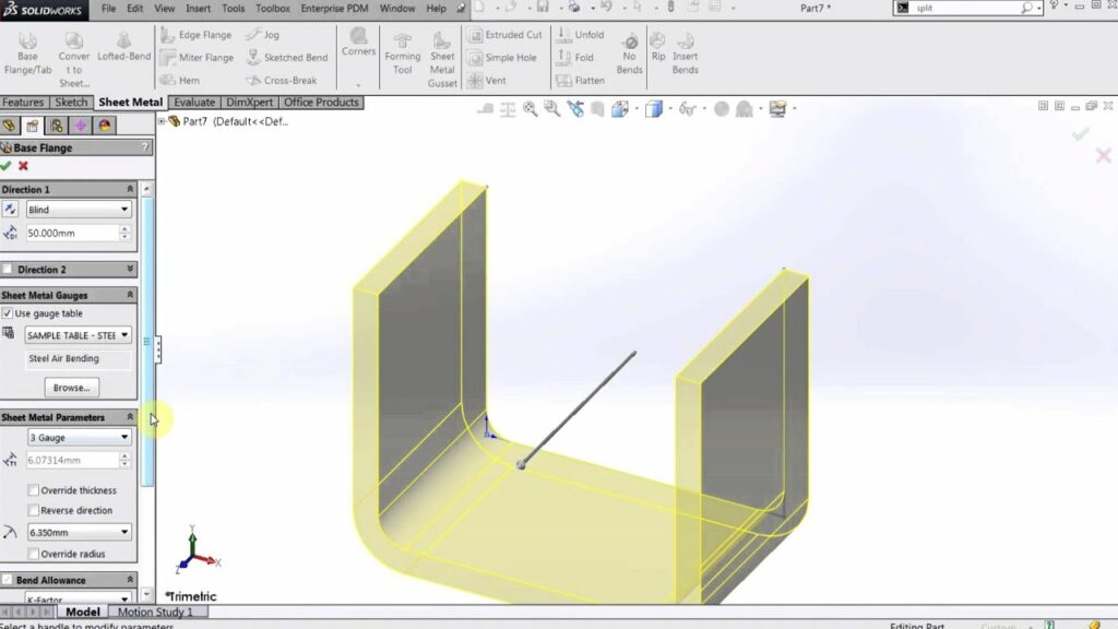
- Add Sheet Metal Features:
- Add sheet metal features such as flanges, bends, tabs, and reliefs to the base profile to create the desired geometry. Use SolidWorks sheet metal tools to define flange lengths, bend angles, and bend radii accurately, ensuring compatibility with manufacturing processes.
- Apply Sheet Metal Rules:
- Apply sheet metal rules and parameters to the part to maintain manufacturability and compliance with design standards. SolidWorks automatically applies default sheet metal rules, such as minimum bend radius and bend relief types, to ensure that the part can be fabricated correctly.
- Unfold and Flatten:
- Unfold the sheet metal part to create a flat pattern representation that can be used for manufacturing and fabrication. SolidWorks provides tools for unfolding and flattening sheet metal parts, allowing designers to visualize and analyze the part’s geometry in its unfolded state.
- Verify Design Intent:
- Verify the design intent of the sheet metal part by reviewing dimensions, clearances, and feature relationships. Use SolidWorks design validation tools to check for interference, collisions, and manufacturability issues that may affect the final part.
- Add Additional Features:
- Add additional features such as holes, cutouts, embosses, and debosses to the sheet metal part as needed. Use SolidWorks modeling tools to create complex features that enhance functionality, aesthetics, and assembly compatibility.
- Document and Detail:
- Document and detail the sheet metal part using SolidWorks drawing tools to create manufacturing drawings, assembly drawings, and part specifications. Include dimensions, tolerances, annotations, and geometric tolerancing information to communicate design intent accurately.
Advanced Sheet Metal Design Techniques: In addition to basic sheet metal modeling tools, SolidWorks offers advanced techniques to enhance sheet metal design capabilities:
- Multi-Body Design:
- Use multi-body design techniques to create complex sheet metal assemblies with multiple components and configurations. SolidWorks allows users to model and manage multiple sheet metal bodies within a single part file, enabling efficient design iteration and optimization.
- Forming Tools:
- Use forming tools in SolidWorks to create custom features and embossments on sheet metal parts, such as louvers, ribs, and embossed logos. Forming tools provide a flexible and efficient way to add decorative and functional elements to sheet metal designs.
- Parametric Design:
- Use parametric design techniques to create configurable and adaptive sheet metal parts that can be easily modified and customized. SolidWorks parametric modeling features allow users to create design tables, equations, and configurations that drive part geometry based on predefined parameters.
Best Practices for Sheet Metal Design: To maximize the effectiveness and efficiency of sheet metal design in SolidWorks, consider the following best practices:
- Design for Manufacturability:
- Design sheet metal parts with manufacturability in mind, considering factors such as material thickness, bend radius, and tooling constraints. Avoid sharp bends, tight radii, and complex geometries that may pose challenges during fabrication.
- Minimize Material Waste:
- Minimize material waste by optimizing sheet metal layouts and nesting parts efficiently. Use SolidWorks nesting tools to arrange parts on sheet metal stock to maximize material utilization and minimize scrap.
- Collaborate with Fabricators:
- Collaborate with sheet metal fabricators and manufacturers early in the design process to ensure that designs are feasible, cost-effective, and compatible with fabrication processes. Consider input from fabricators regarding material selection, tooling requirements, and assembly methods.
- Document Design Intent:
- Document design intent clearly and comprehensively using SolidWorks drawing annotations and notes. Provide detailed instructions, dimensions, and tolerances to guide fabrication, assembly, and quality control processes effectively.
Conclusion: Sheet metal design in SolidWorks is a versatile and powerful tool for creating complex and functional parts for a wide range of applications. By mastering sheet metal modeling techniques and adhering to best practices, you can streamline the design process, optimize part performance, and facilitate efficient fabrication and assembly. Whether you’re a novice or an experienced SolidWorks user, understanding the fundamentals of sheet metal design and exploring advanced techniques will elevate your mechanical design skills and enable you to create innovative and high-quality sheet metal parts with confidence.