Mastering Mechanism Design in Autodesk Inventor: A Comprehensive Guide
Introduction: Autodesk Inventor is a powerful computer-aided design (CAD) software widely used by engineers and designers for creating 3D models of mechanical components, assemblies, and systems. From simple linkages and gears to complex machinery and robotic systems, Inventor provides robust tools for designing, simulating, and analyzing mechanical mechanisms. In this comprehensive guide, we’ll delve into the intricacies of designing mechanisms in Autodesk Inventor, covering everything from component modeling and assembly constraints to motion simulation and optimization.
Section 1: Introduction to Mechanism Design in Autodesk Inventor 1.1 Overview of Autodesk Inventor: Autodesk Inventor is a feature-rich CAD software suite that allows engineers to design and visualize mechanical components and assemblies in 3D. It offers a comprehensive set of tools for creating parametric models, generating engineering drawings, and simulating mechanical behavior. Inventor’s intuitive interface, extensive library of standard parts, and integrated simulation capabilities make it an ideal platform for designing complex mechanical mechanisms.
1.2 Importance of Mechanism Design: Mechanism design is a critical aspect of mechanical engineering, essential for creating systems that convert motion, transmit power, and perform specific tasks. Mechanical mechanisms, such as linkages, cams, gears, and mechanisms, are fundamental building blocks of machines and systems in various industries, including automotive, aerospace, manufacturing, and robotics. By designing mechanisms in Autodesk Inventor, engineers can optimize performance, minimize errors, and accelerate the product development process.
Section 2: Getting Started with Mechanism Design in Autodesk Inventor 2.1 Installation and Setup: To begin designing mechanisms in Autodesk Inventor, users need to install the software on their computer and activate the license. Inventor is available in different editions, including Standard, Professional, and Ultimate, each offering varying levels of functionality and features. Once installed, users can launch Inventor and start creating mechanical models using the intuitive interface and tools.
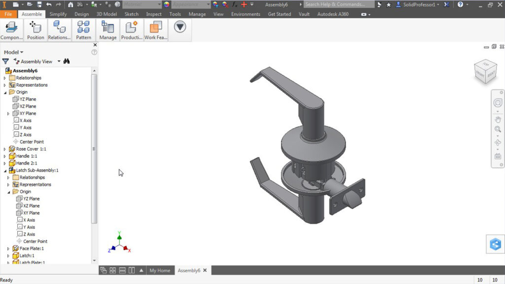
2.2 User Interface Overview: Autodesk Inventor’s user interface consists of several main windows, including the model workspace, browser, and toolbar panels. The model workspace is where users create and edit 3D models of mechanical components and assemblies. The browser panel provides access to model features, components, and constraints, while the toolbar panels contain tools and commands for performing modeling operations, such as sketching, extruding, and constraining.
Section 3: Component Modeling and Assembly Design 3.1 Component Modeling: Inventor provides a range of modeling tools for creating 3D models of mechanical components, such as parts, bodies, and features. Users can create sketches on 2D planes and use sketching tools, such as lines, circles, arcs, and splines, to define geometry. Extrusion, revolve, sweep, and loft features allow users to create solid bodies from sketches, while fillet, chamfer, hole, and pattern features enable users to add detail and complexity to models.
3.2 Assembly Design: Once individual components are modeled, users can assemble them into mechanical assemblies using Autodesk Inventor’s assembly design tools. Users can insert components into the assembly workspace, constrain them to other components using assembly constraints, and define motion relationships between components. Constraints such as mate, flush, tangent, and coincident allow users to simulate real-world interactions between components and ensure proper alignment and functionality.
Section 4: Mechanism Design and Motion Simulation 4.1 Mechanism Design: Inventor’s mechanism design tools allow users to create kinematic relationships between components and simulate mechanical motion within assemblies. Users can define joints, connections, and motion constraints to specify how components interact and move relative to each other. Common types of mechanisms, such as revolute joints, slider joints, cylindrical joints, and gear connections, can be easily created and configured to simulate specific motion behaviors.
4.2 Motion Simulation: Once mechanisms are defined, users can simulate mechanical motion within assemblies using Autodesk Inventor’s motion simulation capabilities. Users can specify input motions, such as rotations, translations, or force inputs, and observe how the assembly responds dynamically. Motion simulation allows users to analyze kinematic behavior, study motion trajectories, detect interference, and evaluate performance metrics such as speed, acceleration, and force.
Section 5: Analysis and Optimization of Mechanisms 5.1 Dynamic Analysis: Inventor’s dynamic analysis tools allow users to perform detailed analysis of mechanical mechanisms and evaluate their dynamic behavior under various operating conditions. Users can simulate dynamic forces, moments, and loads acting on components, and analyze how they affect system performance and stability. Dynamic analysis helps engineers identify potential issues such as resonance, vibration, and impact forces and optimize mechanism designs accordingly.
5.2 Optimization Techniques: In addition to analysis, Autodesk Inventor provides optimization tools for optimizing mechanism designs and improving system performance. Users can use parametric optimization techniques to automatically adjust design parameters, such as component dimensions, material properties, and motion constraints, to optimize specific performance metrics. Inventor’s optimization algorithms help users find optimal solutions that balance competing design objectives and constraints.
Section 6: Real-World Applications and Case Studies 6.1 Automotive Mechanisms: Autodesk Inventor is widely used in the automotive industry for designing and simulating mechanical mechanisms, such as engine systems, suspension systems, and transmission systems. Engineers can use Inventor to model and analyze complex mechanisms, simulate dynamic behavior, and optimize performance characteristics such as efficiency, reliability, and durability. Inventor’s simulation capabilities help automotive engineers develop innovative solutions and bring new products to market faster.
6.2 Robotics and Automation: In the field of robotics and automation, Autodesk Inventor is used for designing and simulating robotic mechanisms, manipulators, and end-effectors. Engineers can use Inventor to model robot kinematics, simulate robot motion, and analyze workspace constraints and reachability. Inventor’s motion simulation tools enable engineers to study robot trajectories, optimize motion paths, and validate control algorithms for robotic systems.
Conclusion: Autodesk Inventor is a versatile and powerful tool for designing mechanical mechanisms, offering users a comprehensive set of features and capabilities for creating, simulating, and analyzing complex systems. By mastering the techniques outlined in this guide and leveraging Inventor’s intuitive interface, extensive modeling tools, and integrated simulation capabilities, users can develop innovative mechanism designs, validate performance, and optimize system behavior with confidence. With its wide range of applications in industries such as automotive, aerospace, robotics, and manufacturing, Autodesk Inventor continues to be a valuable asset for mechanical engineers and designers worldwide, driving innovation and advancement in mechanical engineering and product development.