Mastering Control System Modeling in Simulink: A Comprehensive Guide
Introduction: Simulink is a powerful simulation and modeling environment developed by MathWorks, widely used by engineers and researchers for modeling, simulating, and analyzing dynamic systems. It provides a graphical block diagram interface for building and simulating dynamic systems, including control systems, signal processing systems, and physical systems. In this comprehensive guide, we’ll delve into the intricacies of modeling control systems in Simulink, covering everything from system representation and block selection to simulation setup and analysis.
Section 1: Introduction to Simulink and Control System Modeling 1.1 Overview of Simulink: Simulink is an extension of MATLAB that provides a visual programming environment for modeling, simulating, and analyzing dynamic systems. It offers a vast library of pre-built blocks for building complex systems, as well as customizable blocks for creating custom components. Simulink’s intuitive interface and graphical block diagram approach make it ideal for modeling control systems, where complex interactions between components need to be represented visually.
1.2 Importance of Control System Modeling: Control system modeling is a fundamental aspect of engineering, essential for designing and analyzing systems that regulate and control the behavior of dynamic processes. By modeling control systems in Simulink, engineers can simulate system dynamics, design and optimize controller algorithms, and evaluate system performance under various operating conditions. Control system modeling helps engineers understand system behavior, predict system responses, and tune controller parameters for desired performance.
Section 2: Getting Started with Simulink 2.1 Installation and Setup: To begin using Simulink, users need to have MATLAB installed on their computer, as Simulink is integrated with MATLAB and relies on MATLAB’s computational capabilities. Once MATLAB is installed, users can launch Simulink from the MATLAB command window or desktop toolbar. Simulink provides a user-friendly interface with tools and menus for creating and editing models, configuring simulations, and analyzing results.
2.2 User Interface Overview: Simulink’s user interface consists of several main windows, including the model window, library browser, and simulation window. The model window is where users create and edit block diagrams, while the library browser provides access to pre-built blocks and libraries. The simulation window displays simulation results, plots, and scope displays during simulation runs. Users can customize the layout and appearance of the interface to suit their preferences.
Section 3: Building Control System Models in Simulink 3.1 Block Selection: Simulink provides a vast library of pre-built blocks for modeling various components of control systems, including sensors, actuators, controllers, and plant models. Users can browse the block libraries, search for specific blocks, and drag-and-drop them onto the model window to build control system models. Blocks are connected using signal lines to represent the flow of signals between components.
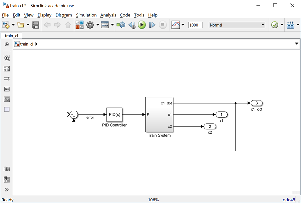
3.2 System Representation: Control systems are typically represented in Simulink as block diagrams, where blocks represent system components and signal lines represent the flow of signals between components. Control system models in Simulink can range from simple single-input/single-output (SISO) systems to complex multi-input/multi-output (MIMO) systems. Users can organize blocks into subsystems and hierarchies to manage complexity and improve readability.
Section 4: Configuring Simulation Parameters 4.1 Simulation Settings: Before running simulations, users need to configure simulation parameters in Simulink to define the simulation duration, solver options, and other simulation settings. Users can specify simulation start and stop times, time step sizes, and solver algorithms to control simulation accuracy and performance. Simulink provides various solver options, including fixed-step and variable-step solvers, to accommodate different types of dynamic systems and simulation requirements.
4.2 Model Initialization: In addition to simulation settings, users may need to specify initial conditions and input signals for control system models in Simulink. Initial conditions define the starting state of the system, such as initial states of integrators and initial values of system variables. Input signals represent external disturbances, setpoints, or reference signals applied to the system during simulation. By configuring model initialization parameters, users can ensure accurate and consistent simulation results.
Section 5: Running Simulations and Analyzing Results 5.1 Simulation Control: Once simulation settings are configured, users can run simulations in Simulink by clicking the “Run” button or using keyboard shortcuts. Simulink’s simulation engine computes system responses based on the specified model dynamics and input signals, generating simulation results in real-time. Users can monitor simulation progress, pause and resume simulations, and visualize simulation outputs during simulation runs.
5.2 Result Analysis: After simulation completion, Simulink provides tools for analyzing simulation results and visualizing system behavior. Users can plot simulation outputs, such as time-domain responses, frequency responses, and step responses, to assess system performance and stability. Simulink’s scope displays, XY plots, and spectrum analyzers allow users to visualize signals, compare responses, and extract performance metrics from simulation data.
Section 6: Advanced Features and Techniques 6.1 Model Validation and Verification: Simulink offers advanced validation and verification tools for assessing the accuracy and reliability of control system models. Users can perform model validation by comparing simulation results with analytical solutions, empirical data, or experimental measurements. Simulink’s model verification tools allow users to analyze model consistency, detect errors or inconsistencies, and perform sensitivity analysis to assess model robustness and reliability.
6.2 Model Optimization and Parameter Estimation: In addition to model validation, Simulink provides tools for optimizing control system models and estimating model parameters from experimental data. Users can use optimization algorithms to tune controller parameters, optimize system performance, and minimize control errors. Simulink’s parameter estimation tools allow users to identify model parameters from input-output data, perform system identification, and calibrate models to match real-world behavior.
Section 7: Real-World Applications and Case Studies 7.1 Industrial Control Systems: Simulink is widely used in industry for modeling and simulating industrial control systems, such as automotive control systems, aerospace systems, and manufacturing processes. Engineers can use Simulink to design and optimize controller algorithms, validate control strategies, and analyze system performance under realistic operating conditions. Simulink’s simulation capabilities help engineers improve system efficiency, reliability, and safety in industrial applications.
7.2 Educational Use and Research: Simulink is extensively used in educational institutions and research laboratories for teaching control theory, conducting laboratory experiments, and performing academic research. Students and researchers can use Simulink to simulate and analyze control systems, explore control concepts, and implement control algorithms in real-time. Simulink’s interactive environment and visualization tools make it an ideal platform for hands-on learning and research in the field of control engineering.
Conclusion: Simulink is a versatile and powerful tool for modeling control systems, offering users a comprehensive set of features and capabilities for designing, simulating, and analyzing dynamic systems. By mastering the techniques outlined in this guide and leveraging Simulink’s intuitive interface, extensive block library, and advanced simulation engine, users can develop innovative control system models, validate controller designs, and optimize system performance with confidence. With its wide range of applications in engineering education, research, and industry, Simulink continues to be a valuable asset for control engineers and researchers worldwide, advancing the field of control engineering and enabling the development of intelligent and autonomous systems.