Mastering Schematic Design with SolidWorks Electrical: A Comprehensive Guide
Introduction: SolidWorks Electrical is a powerful software solution developed by Dassault Systèmes, tailored specifically for electrical design and documentation tasks. It offers a comprehensive set of tools for creating schematics, generating panel layouts, and producing detailed manufacturing documentation for electrical systems. In this extensive guide, we will explore the intricacies of using SolidWorks Electrical for schematic design, covering everything from project setup and symbol creation to wire routing and annotation.
Section 1: Introduction to SolidWorks Electrical 1.1 Overview of SolidWorks Electrical: SolidWorks Electrical is an integrated software solution designed to streamline the electrical design process, from concept to manufacturing. It provides a unified environment for schematic design, 3D panel layout, and collaboration between electrical and mechanical design teams. SolidWorks Electrical offers a rich library of electrical symbols, components, and manufacturer parts, making it an ideal tool for creating accurate and efficient electrical schematics.
1.2 Importance of Schematic Design: Schematic design is a critical phase in the electrical engineering workflow, where engineers translate functional requirements into graphical representations of electrical systems. Accurate and well-organized schematics serve as blueprints for the construction, installation, and maintenance of electrical systems, ensuring clarity, consistency, and compliance with industry standards. SolidWorks Electrical simplifies the schematic design process, enabling engineers to create professional-quality schematics quickly and efficiently.
Section 2: Getting Started with SolidWorks Electrical 2.1 Installation and Setup: To begin using SolidWorks Electrical, users need to install the software on their computer and activate the license. SolidWorks Electrical is available in different editions, including Schematic, 3D, and Professional, each offering varying levels of functionality and features. Once installed, users can launch SolidWorks Electrical and create new projects to start designing electrical schematics.
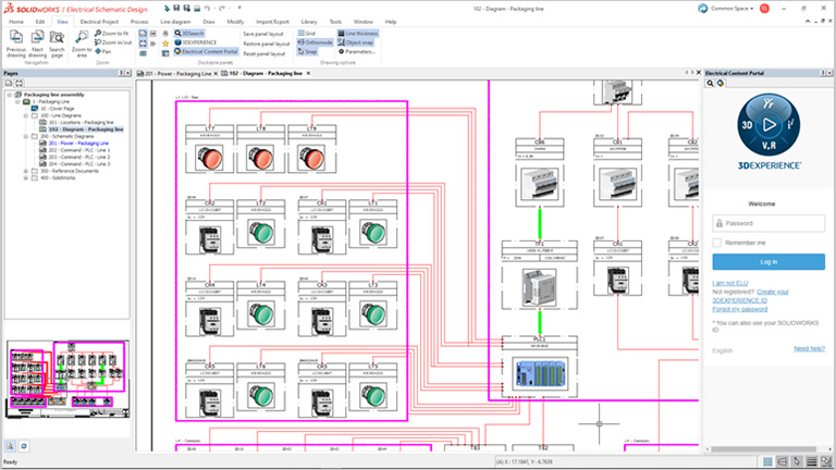
2.2 User Interface Overview: SolidWorks Electrical provides a user-friendly interface with intuitive tools and menus for schematic design and documentation. The main workspace consists of the schematic editor, where users create and edit electrical schematics using predefined symbols and components. The project manager window allows users to organize project files, manage libraries, and access project documentation. Users can customize the interface layout and toolbars to suit their preferences.
Section 3: Project Setup and Configuration 3.1 Creating a New Project: To create a new project in SolidWorks Electrical, users need to define project properties such as project name, location, and units. Users can specify project templates, drawing formats, and title blocks to standardize project documentation and ensure consistency across designs. SolidWorks Electrical provides templates for various industries and standards, including ANSI, IEC, and JIC, to meet specific design requirements.
3.2 Library Management: SolidWorks Electrical includes a comprehensive library of electrical symbols, components, and manufacturer parts, organized into categories for easy access. Users can customize and expand the library by adding custom symbols, macros, and 3D models, or importing parts from external sources. SolidWorks Electrical’s intelligent library management tools ensure that users have access to the latest component data and maintain consistency throughout the design process.
Section 4: Schematic Design and Symbol Creation 4.1 Symbol Insertion: In SolidWorks Electrical, users can insert electrical symbols and components into schematics using the symbol library browser. Symbols can be dragged and dropped onto the schematic editor and connected with wires to represent electrical connections and circuits. SolidWorks Electrical provides a rich library of standard symbols for common electrical components, such as switches, relays, motors, and connectors, as well as specialized symbols for specific applications.
4.2 Custom Symbol Creation: In addition to standard symbols, SolidWorks Electrical allows users to create custom symbols and macros to represent unique or proprietary components. Users can define symbol attributes, such as pin connections, properties, and annotations, using the symbol editor. Custom symbols can be saved to the project library for reuse in future designs, ensuring consistency and efficiency in schematic design.
Section 5: Wire Routing and Connection Management 5.1 Wire Routing: SolidWorks Electrical simplifies the process of routing wires and cables in electrical schematics using automated routing tools. Users can specify wire paths, define wire types and properties, and generate wire routes automatically based on predefined rules and constraints. SolidWorks Electrical ensures accurate wire lengths, minimizes crossing and overlapping wires, and generates wire reports for documentation and manufacturing purposes.
5.2 Connection Management: Managing electrical connections is essential for ensuring proper signal flow and electrical continuity in schematics. SolidWorks Electrical provides tools for managing wire connections, including automatic wire numbering, terminal strip management, and cross-referencing. Users can define connection points, assign wire numbers, and generate connection reports to track wire routing and verify connectivity throughout the design.
Section 6: Annotation and Documentation 6.1 Annotation Tools: SolidWorks Electrical offers a range of annotation tools for adding text, labels, symbols, and annotations to electrical schematics. Users can annotate components with part numbers, descriptions, and manufacturer data, as well as add comments, notes, and callouts to clarify design intent. SolidWorks Electrical’s intelligent annotation features ensure consistency and accuracy in documentation, minimizing errors and improving communication between design teams.
6.2 Documentation Generation: Once schematics are finalized, SolidWorks Electrical allows users to generate comprehensive documentation, including bill of materials (BOMs), wire lists, cable schedules, and terminal plans. Users can customize document templates, add custom fields and properties, and export documentation to various formats, such as PDF, Excel, and AutoCAD DXF. SolidWorks Electrical’s documentation tools streamline the production of manufacturing documentation and facilitate collaboration with suppliers and contractors.
Section 7: Real-World Applications and Case Studies 7.1 Industrial Electrical Design: SolidWorks Electrical is widely used in industrial settings for designing electrical systems, control panels, and machinery. Engineers can use SolidWorks Electrical to create detailed schematics, panel layouts, and wiring diagrams for complex electrical systems, such as manufacturing automation, HVAC control, and process instrumentation. SolidWorks Electrical’s integrated design environment improves productivity, reduces errors, and accelerates time-to-market for industrial products and systems.
7.2 Building Automation and MEP: In the field of building automation and MEP (mechanical, electrical, plumbing) design, SolidWorks Electrical is used for designing electrical distribution systems, lighting controls, and fire alarm systems. Engineers can use SolidWorks Electrical to create floor plans, riser diagrams, and schematic drawings for building electrical systems, ensuring compliance with local building codes and regulations. SolidWorks Electrical’s collaborative design tools enable MEP engineers to coordinate with architects, contractors, and other stakeholders to deliver integrated building systems.
Conclusion: SolidWorks Electrical is a versatile and powerful tool for schematic design, offering users a comprehensive set of features and capabilities for creating accurate and efficient electrical schematics. By mastering the techniques outlined in this guide and leveraging SolidWorks Electrical’s intuitive interface, extensive symbol library, and automated design tools, users can streamline the electrical design process, improve documentation quality, and accelerate project delivery with confidence. With its wide range of applications in industries such as manufacturing, building automation, and MEP design, SolidWorks Electrical continues to be a valuable asset for electrical engineers and designers worldwide, driving innovation and efficiency in electrical design and documentation.