Unlocking Efficiency and Precision: A Comprehensive Guide to Using the Panel Layout Annotation Tool in Autodesk Electrical

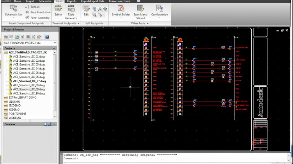
Autodesk Electrical empowers users with a suite of powerful tools to streamline the design process, and among them, the Panel Layout Annotation tool stands out for its ability to enhance precision and efficiency in panel layout design. This comprehensive guide will delve into the intricacies of utilizing this tool, providing step-by-step instructions, best practices, and expert insights to help you master the art of panel layout annotation in Autodesk Electrical.
Understanding the Panel Layout Annotation Tool
The Panel Layout Annotation tool in Autodesk Electrical is designed to simplify the process of annotating panel layouts, allowing users to add annotations, labels, and tags to panel components with ease. By leveraging this tool effectively, users can enhance clarity, organization, and documentation in panel layout designs, ultimately improving communication and collaboration among project stakeholders.
Step-by-Step Guide to Using the Panel Layout Annotation Tool
Step 1: Accessing the Panel Layout Annotation Tool
- Launch Autodesk Electrical and open the panel layout drawing you wish to annotate.
- Navigate to the “Annotate” tab on the ribbon toolbar.
- Click on the “Panel Layout Annotation” tool icon to activate the annotation mode.
Step 2: Adding Annotations to Panel Components
- With the annotation mode activated, click on the panel components you wish to annotate, such as circuit breakers, terminals, or wires.
- Select the appropriate annotation type from the annotation palette, such as text labels, wire numbers, or terminal tags.
- Position the annotation accordingly on the panel component and click to place it.
Step 3: Customizing Annotation Properties
- After placing an annotation, you can customize its properties by double-clicking on the annotation to access the properties dialog box.
- Adjust properties such as text size, font, color, and alignment to meet your specific requirements.
- Save custom annotation styles for reuse across projects by creating annotation templates.
Step 4: Editing and Managing Annotations
- To edit or modify existing annotations, simply select the annotation you wish to edit and use the editing tools available in the annotation palette.
- Manage annotations by grouping, aligning, or distributing them using the annotation manipulation tools.
Step 5: Reviewing and Finalizing Annotations
- Once all annotations have been added and customized, review the panel layout design to ensure accuracy and completeness.
- Save the annotated panel layout drawing and share it with project stakeholders for review and approval.
Best Practices for Using the Panel Layout Annotation Tool
To optimize your use of the Panel Layout Annotation tool in Autodesk Electrical, consider the following best practices:
- Standardization: Establish standardized annotation styles and templates to maintain consistency across panel layout designs.
- Clarity: Use clear and concise annotations to ensure readability and comprehension by all stakeholders.
- Organization: Arrange annotations logically and systematically to facilitate easy navigation and reference.
- Documentation: Document annotation conventions, standards, and guidelines for reference and training purposes.
Conclusion
The Panel Layout Annotation tool in Autodesk Electrical is a valuable asset for designers seeking to enhance precision, efficiency, and communication in panel layout design. By following the step-by-step guide and best practices outlined in this comprehensive guide, users can harness the full potential of this tool to annotate panel layouts effectively, streamline the design process, and achieve superior results in their projects. Whether you’re a seasoned professional or a novice user, mastering the Panel Layout Annotation tool will empower you to elevate your panel layout design capabilities to new heights.


