Mastering Electronic Circuit Simulation with SPICE: A Comprehensive Guide

Introduction: SPICE (Simulation Program with Integrated Circuit Emphasis) is a powerful tool widely used for electronic circuit simulation, analysis, and design. Originally developed at the University of California, Berkeley in the 1970s, SPICE has become an industry-standard simulation software for engineers, researchers, and educators in the field of electronics. In this comprehensive guide, we will delve into the process of using SPICE for electronic circuit simulation, covering key concepts, modeling techniques, simulation methods, and best practices to help users master the art of electronic circuit design and analysis.
Section 1: Understanding SPICE Simulation
1.1 Importance of Electronic Circuit Simulation: Electronic circuit simulation plays a crucial role in the design, analysis, and optimization of electronic systems, providing engineers with insights into circuit behavior, performance, and functionality before physical prototyping or implementation. Simulation allows engineers to predict circuit responses, verify design specifications, troubleshoot issues, and explore design alternatives in a virtual environment, saving time, cost, and resources in the product development process.
1.2 Overview of SPICE Software: SPICE is a versatile simulation software package designed for modeling and simulating electronic circuits, including analog circuits, digital circuits, and mixed-signal circuits. It offers a rich set of simulation capabilities, including transient analysis, AC analysis, DC analysis, parametric sweeps, Monte Carlo analysis, and sensitivity analysis, to evaluate circuit behavior under various operating conditions and stimuli. SPICE supports a wide range of circuit elements, models, and simulation techniques, making it suitable for diverse applications in electronics design and education.
Section 2: Getting Started with SPICE Simulation
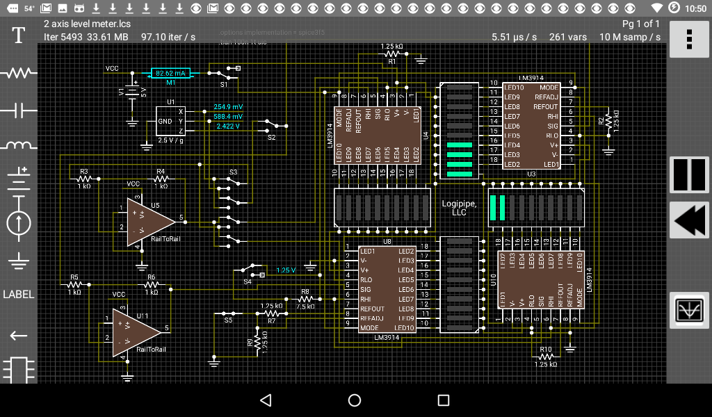
2.1 Circuit Modeling and Netlisting: Begin by creating a circuit schematic using a SPICE-compatible schematic capture tool or text editor, defining circuit elements, connections, and parameters. SPICE circuits are typically represented using a netlist format, which lists component names, node connections, and parameter values in a structured text file. Use standard component symbols, such as resistors, capacitors, inductors, voltage sources, current sources, and semiconductor devices, to model circuit elements accurately.
2.2 Circuit Analysis and Simulation Commands: Define simulation commands and directives in the SPICE netlist to specify simulation type, duration, analysis options, and output formats. Common SPICE simulation commands include:
- .TRAN: Transient analysis command for simulating circuit behavior over a specified time interval.
- .AC: AC analysis command for frequency-domain analysis of circuit response.
- .DC: DC analysis command for sweeping parameter values and plotting DC characteristics.
- .PARAM: Parameter definition command for defining symbolic parameters and expressions.
- .PRINT: Output printing command for displaying simulation results or saving data to a file.
- .OPTIONS: Simulation options command for configuring solver settings, convergence criteria, and analysis options.
2.3 Component Modeling and Parameterization: Specify component models, values, and parameters in the SPICE netlist to accurately represent circuit behavior and characteristics. Use manufacturer datasheets, component specifications, or model libraries to select appropriate models for resistors, capacitors, inductors, diodes, transistors, operational amplifiers, and other circuit elements. Parameterize component models with nominal values, tolerances, temperature coefficients, and operating conditions to capture device variability and environmental effects.
2.4 Simulation Setup and Execution: Configure simulation settings, such as simulation type, time step size, convergence criteria, and output options, before running the SPICE simulation. Ensure that the netlist syntax is correct, components are properly connected, and simulation directives are accurately specified to avoid errors or simulation failures. Execute the SPICE simulation using a compatible SPICE simulator or simulation environment to solve circuit equations, simulate circuit response, and generate simulation results.
Section 3: Analyzing SPICE Simulation Results
3.1 Transient Analysis: Analyze transient simulation results to understand circuit behavior over time, including startup transients, transient responses, and settling behavior. Plot time-domain waveforms of circuit voltages, currents, node voltages, and device characteristics to visualize circuit dynamics, identify signal transitions, and assess circuit performance under transient conditions.
3.2 AC Analysis: Perform AC analysis to investigate circuit frequency response, gain, phase shift, and impedance characteristics across a range of frequencies. Plot frequency-domain magnitude and phase plots of circuit transfer functions, impedance curves, and Bode plots to analyze circuit stability, resonance, and frequency-dependent behavior under AC excitation.
3.3 DC Analysis: Conduct DC analysis to study circuit DC operating points, voltage/current distributions, and DC bias conditions. Plot DC characteristics, such as IV curves, load lines, and operating point solutions, to analyze transistor biasing, voltage divider circuits, and DC voltage/current distributions in electronic circuits.
3.4 Parametric Sweeps and Sensitivity Analysis: Perform parametric sweeps and sensitivity analysis to explore circuit behavior under varying parameter values, component tolerances, or environmental conditions. Sweep parameter values, such as resistor values, capacitor values, or temperature coefficients, to assess their impact on circuit performance, stability, and sensitivity to variations.
Section 4: Best Practices for SPICE Simulation
4.1 Component Modeling and Model Selection: Use accurate and validated component models for circuit elements to ensure simulation fidelity and reliability. Select component models based on device specifications, datasheet parameters, or manufacturer recommendations to capture device characteristics, nonlinear behavior, and temperature effects accurately.
4.2 Simulation Convergence and Stability: Monitor simulation convergence, numerical stability, and solution accuracy during SPICE simulations to ensure reliable and accurate results. Adjust simulation settings, solver options, and convergence criteria to mitigate numerical instabilities, convergence issues, or oscillations and improve simulation performance and reliability.
4.3 Sensitivity to Initial Conditions and Inputs: Evaluate circuit sensitivity to initial conditions, boundary conditions, and input stimuli to understand circuit behavior and predict response variations under different operating conditions. Assess sensitivity trends, parameter sensitivities, and input dependencies to optimize circuit design, performance, and robustness.
4.4 Model Validation and Verification: Validate and verify SPICE models against experimental data, analytical solutions, or manufacturer specifications to ensure model accuracy, reliability, and predictive capability. Compare simulation results with empirical measurements, test data, or industry standards to validate model fidelity and credibility for electronic circuit design and analysis.
Conclusion: SPICE simulation is an indispensable tool for electronic circuit design, analysis, and optimization, providing engineers with a virtual environment to explore circuit behavior, verify design specifications, and optimize performance before physical prototyping or implementation. By following best practices, modeling techniques, and simulation methodologies outlined in this guide, users can leverage SPICE’s capabilities to design, analyze, and troubleshoot electronic circuits effectively. SPICE simulation empowers engineers to innovate, iterate, and refine electronic designs, driving advancements in electronics technology and accelerating product development in diverse industries and applications.


