Navigating the Depths: A Comprehensive Exploration of the User Coordinate System in AutoCAD
Introduction:
AutoCAD, a flagship software in the realm of computer-aided design (CAD), has revolutionized the way architects, engineers, and designers conceptualize and create drawings. At the heart of AutoCAD’s functionality lies the User Coordinate System (UCS), a fundamental aspect that dictates the orientation and precision of objects within the drawing environment. This article embarks on a detailed journey to unravel the intricacies of the User Coordinate System in AutoCAD, examining its significance, customization options, and its impact on drafting precision.
I. The Foundation of AutoCAD: User Coordinate System (UCS)
- Defining the User Coordinate System: The User Coordinate System in AutoCAD is a pivotal concept that establishes a reference framework for creating and manipulating drawings. It serves as a coordinate system within the drawing space, defining the X, Y, and Z axes, thus determining the spatial relationships of objects.
- Primary Axes Orientation: The default orientation of the UCS in AutoCAD follows the right-hand rule, where the positive X-axis extends to the right, the positive Y-axis extends upward, and the positive Z-axis extends outward from the drawing plane. Understanding this fundamental orientation is crucial for accurate drawing creation.
II. Significance of the UCS in AutoCAD:
- Precision and Consistency: The UCS plays a pivotal role in ensuring precision and consistency in drafting. By defining a standard coordinate system, AutoCAD users can maintain accuracy throughout the design process, aiding in the creation of geometrically precise and standardized drawings.
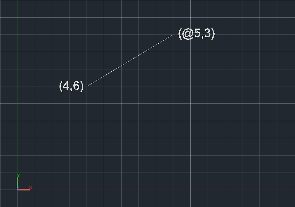
- Coordinate Input: When specifying points or distances in AutoCAD, the UCS provides the reference framework for entering coordinates. Users can input coordinates relative to the UCS origin or switch to alternative coordinate systems to align with specific design requirements.
III. Customizing the UCS in AutoCAD:
- Dynamic UCS: AutoCAD offers a feature known as Dynamic UCS, which dynamically adjusts the UCS to align with a face of a 3D object. This capability simplifies the creation of objects on non-standard planes, enhancing workflow efficiency in 3D modeling.
- UCS Icon Customization: The UCS icon, a visual representation of the coordinate system, can be customized in AutoCAD to suit user preferences. Altering the appearance and positioning of the UCS icon enhances visibility and aids in maintaining spatial awareness during the design process.
IV. UCS in 2D and 3D Environments:
- UCS in 2D Drafting: In a 2D drafting environment, the UCS primarily dictates the orientation of objects within the XY plane. Users can manipulate the UCS to simplify the creation of objects at various angles, streamlining the drafting process.
- UCS in 3D Modeling: For 3D modeling, the UCS extends into the Z-axis, allowing users to define spatial relationships in three dimensions. The flexibility of the UCS in a 3D environment empowers designers to create complex and accurate three-dimensional models.
V. UCS Command and Navigation:
- UCS Command: AutoCAD provides a dedicated UCS command, allowing users to manipulate the coordinate system based on specific requirements. By accessing this command, designers can rotate, align, or reset the UCS to cater to the demands of the drawing.
- UCS Navigation: Navigating the UCS involves using commands such as “UCS,” “UCSICON,” and “PLAN” to switch between different views, customize the UCS icon, and establish planar orientations. Mastery of these commands enhances the user’s control over the drawing environment.
VI. Advanced Applications of UCS in AutoCAD:
- Sectional Views: The UCS proves invaluable when creating sectional views in AutoCAD. By aligning the UCS with a desired cutting plane, designers can generate accurate and visually informative section views of complex 3D models.
- Isometric Drawing: AutoCAD users often employ the UCS to create isometric drawings, where the coordinate system is adjusted to align with isometric planes. This technique simplifies the representation of three-dimensional objects in two dimensions.
VII. Troubleshooting and Tips:
- UCS-related Issues: Users may encounter challenges related to UCS manipulation or orientation. Common issues include unintended changes to the UCS or difficulties in navigating the drawing space. Troubleshooting tips, such as using the “UCS” command or resetting the UCS, can aid in resolving such issues.
- Best Practices: Implementing best practices for UCS usage involves maintaining consistency, labeling UCS changes for documentation, and leveraging dynamic UCS for efficient 3D modeling. Adhering to these practices contributes to a streamlined and organized design workflow.
VIII. Collaborative Workflows and UCS:
- UCS and File Collaboration: When collaborating on AutoCAD projects, understanding and maintaining consistency in the UCS is crucial for seamless file exchange. Standardizing UCS orientation and communicating UCS-related changes ensure collaborative efficiency.
- UCS in Multi-disciplinary Projects: In multi-disciplinary projects involving architects, structural engineers, and MEP (Mechanical, Electrical, Plumbing) designers, a standardized UCS becomes paramount. It facilitates coordination and integration of diverse design elements within a unified reference framework.
IX. Future Developments and Evolving Trends:
- Integrating AI and Automation: As AutoCAD continues to evolve, the integration of artificial intelligence (AI) and automation may impact how the UCS is utilized. Smart UCS adjustments based on user behavior or predictive modeling could enhance efficiency and user experience.
- Virtual and Augmented Reality: The advent of virtual and augmented reality technologies may usher in new ways of interacting with the UCS. Visualizing the coordinate system in a three-dimensional virtual space could revolutionize the design process, providing an immersive and intuitive experience.
Conclusion:
The User Coordinate System in AutoCAD stands as a foundational element that shapes the way designers navigate and create within the software. From its role in ensuring precision and consistency to its customization options and advanced applications in 3D modeling, the UCS is an indispensable tool in the hands of AutoCAD users. This comprehensive exploration has aimed to demystify the complexities of the User Coordinate System, providing insights into its significance, customization features, troubleshooting techniques, and its evolving role in the ever-changing landscape of computer-aided design. As AutoCAD continues to be at the forefront of innovation in the field, a thorough understanding of the UCS remains essential for harnessing the full potential of this powerful design tool.