Mastering Circuit Simulation with Multisim: A Comprehensive Guide
Introduction: Multisim is a powerful electronic design automation (EDA) software developed by National Instruments, widely used by engineers, educators, and students for simulating and analyzing electronic circuits. It provides a user-friendly interface, extensive component libraries, and advanced simulation capabilities for designing, testing, and optimizing circuits in various applications. In this comprehensive guide, we’ll delve into the intricacies of using Multisim for circuit simulation, covering everything from circuit design and component selection to simulation setup and result analysis.
Section 1: Introduction to Multisim and Circuit Simulation 1.1 Overview of Multisim: Multisim is a versatile circuit simulation platform that allows users to design, simulate, and analyze electronic circuits with ease. It provides a graphical schematic capture environment where users can create and edit circuit schematics using a wide range of electronic components, such as resistors, capacitors, inductors, transistors, and integrated circuits. Multisim’s simulation engine enables users to perform transient, AC, DC, and frequency domain analysis of circuits, helping to verify functionality, analyze performance, and troubleshoot design issues.
1.2 Importance of Circuit Simulation: Circuit simulation is a crucial step in the electronic design process, allowing engineers to validate circuit designs and predict their behavior before prototyping and manufacturing. By simulating circuits in software like Multisim, engineers can verify circuit functionality, optimize component values, and identify design flaws or performance limitations early in the design process. Circuit simulation helps reduce development time, minimize prototyping costs, and improve overall design reliability and performance.
Section 2: Getting Started with Multisim 2.1 Installation and Setup: To begin using Multisim, users need to install the software on their computer and activate the license. Multisim is available in different editions, including Student, Professional, and Power Pro, each offering varying levels of functionality and features. Once installed, users can launch Multisim and start creating and simulating circuits using the intuitive graphical interface.
2.2 User Interface Overview: Multisim provides a user-friendly interface with intuitive tools and menus for circuit design and simulation. The main workspace consists of a schematic editor where users can draw circuit schematics using components from the component library. Users can access various menus, toolbars, and panels to perform actions such as adding components, connecting wires, configuring simulation settings, and analyzing simulation results.
Section 3: Circuit Design and Component Selection 3.1 Component Libraries: Multisim includes a comprehensive library of electronic components, covering a wide range of categories such as passive components, active components, analog and digital ICs, power sources, and measurement instruments. Users can browse the component library, search for specific components, and drag-and-drop them onto the schematic editor to build circuit schematics.
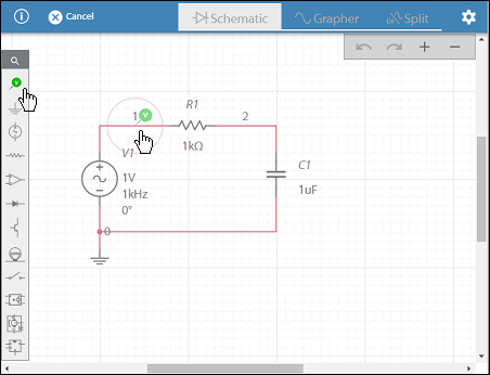
3.2 Creating Circuit Schematics: Using the schematic editor in Multisim, users can create circuit schematics by placing components on the workspace and connecting them with wires. Components can be arranged and grouped to organize the circuit layout and improve readability. Users can customize component properties, such as resistance values, capacitance values, transistor models, and operational amplifier parameters, to match the desired circuit configuration.
Section 4: Simulation Setup and Analysis 4.1 Simulation Types: Multisim supports various types of circuit simulations, including transient analysis, AC analysis, DC analysis, and frequency domain analysis. Transient analysis simulates the time-domain behavior of circuits over a specified time interval, while AC analysis analyzes circuit behavior in the frequency domain. DC analysis computes DC operating points and voltages in the circuit, and frequency domain analysis calculates frequency response and transfer functions.
4.2 Simulation Setup: Before running simulations, users need to configure simulation settings, such as simulation type, analysis parameters, and simulation options. Users can specify simulation time, step size, and initial conditions for transient analysis, frequency range and number of points for AC analysis, and operating point voltages for DC analysis. Multisim provides options for controlling convergence criteria, simulation tolerances, and output formats.
Section 5: Running Simulations and Analyzing Results 5.1 Simulation Control: Once simulation settings are configured, users can run simulations in Multisim by clicking the “Run” button or using keyboard shortcuts. Multisim’s simulation engine computes circuit responses based on the specified analysis type and parameters, generating simulation results in real-time. Users can monitor simulation progress, pause and resume simulations, and abort simulations if necessary.
5.2 Result Analysis: After simulation completion, Multisim provides tools for analyzing simulation results and visualizing circuit behavior. Users can plot waveforms, graphs, and charts to display voltage and current waveforms, frequency responses, Bode plots, and transient responses. Multisim’s waveform analyzer allows users to measure signal characteristics, such as amplitudes, frequencies, rise times, and fall times, and perform statistical analysis on simulation data.
Section 6: Advanced Features and Techniques 6.1 Parameter Sweeps and Monte Carlo Analysis: Multisim allows users to perform parameter sweeps and Monte Carlo analysis to study circuit behavior under different operating conditions and component variations. Parameter sweeps involve varying component values, such as resistor values or capacitor values, over a range of values to evaluate their impact on circuit performance. Monte Carlo analysis involves simulating circuits with randomized component values to assess circuit robustness and reliability.
6.2 Custom Models and Subcircuits: In addition to standard library components, Multisim enables users to create custom models and subcircuits to represent complex or proprietary components. Users can define custom component models using SPICE (Simulation Program with Integrated Circuit Emphasis) syntax or create hierarchical subcircuits to encapsulate and reuse circuit designs. Custom models and subcircuits enhance circuit simulation accuracy and enable users to model specialized components or circuits not available in the standard component library.
Section 7: Real-World Applications and Case Studies 7.1 Electronic Circuit Design: Multisim is widely used in the design of electronic circuits for various applications, including analog and digital circuits, power electronics, communication systems, and sensor interfaces. Engineers can use Multisim to prototype circuit designs, verify functionality, and optimize performance before prototyping and production. Multisim’s simulation capabilities help reduce design iterations, minimize development costs, and accelerate time-to-market for electronic products and systems.
7.2 Educational Use and Research: Multisim is extensively used in educational institutions and research laboratories for teaching electronics principles, conducting laboratory experiments, and performing academic research. Students and researchers can use Multisim to learn circuit theory, explore circuit behavior, and conduct virtual experiments in electronics and electrical engineering courses. Multisim’s intuitive interface and simulation capabilities make it an ideal tool for hands-on learning and research in the field of electronics.
Conclusion: Multisim is a versatile and powerful tool for circuit simulation and analysis, offering users a comprehensive set of features and capabilities for designing, testing, and optimizing electronic circuits. By mastering the techniques outlined in this guide and leveraging Multisim’s intuitive interface, extensive component library, and advanced simulation engine, users can develop innovative circuit designs, validate circuit functionality, and optimize performance with confidence. With its wide range of applications in engineering education, research, and industry, Multisim continues to be a valuable asset for electronics enthusiasts and professionals alike, shaping the future of electronic design and innovation.