Building Control Systems and PID Loops in LabVIEW
Introduction
Control systems play a crucial role in engineering and automation, regulating processes and ensuring desired outcomes by continuously adjusting variables. LabVIEW (Laboratory Virtual Instrument Engineering Workbench), developed by National Instruments, provides a powerful platform for designing and implementing control systems. This comprehensive guide explores the fundamentals, techniques, and practical applications of building control systems and PID (Proportional-Integral-Derivative) loops in LabVIEW.
Understanding Control Systems
What is a Control System?
A control system is a system that manages, commands, directs, or regulates the behavior of other devices or systems to achieve desired results. It consists of:
- Plant: The process or system being controlled (e.g., a motor, a temperature chamber).
- Controller: The component that adjusts the plant’s inputs based on feedback to achieve desired outputs.
- Sensors: Devices that measure the system’s output or state variables (e.g., temperature sensors, position encoders).
- Actuators: Devices that apply the control inputs to the plant (e.g., motors, heaters).
Types of Control Systems
- Open-Loop Control: Input is set without feedback; no correction is made based on the output.
- Closed-Loop Control (Feedback Control): Input is adjusted based on feedback from the system’s output, ensuring desired performance and stability.
PID Control
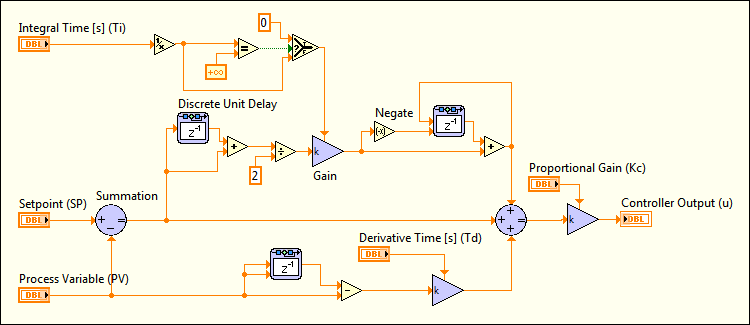
PID control is a common feedback control technique that calculates an error signal as the difference between a desired setpoint (SP) and a measured process variable (PV). The PID controller adjusts the system’s control input (manipulated variable, MV) to minimize this error over time.
- Proportional (P) Term: Directly proportional to the current error, providing immediate response to changes.
- Integral (I) Term: Accumulates past errors over time, eliminating steady-state error.
- Derivative (D) Term: Predicts future error trends, improving transient response and stability.
LabVIEW for Control Systems
Overview of LabVIEW
LabVIEW offers a graphical programming environment ideal for designing and deploying control systems:
- Graphical Programming: Develop control algorithms using a visual approach with intuitive dataflow diagrams.
- Modularity: Easily create and reuse components (subVIs) for efficient system design.
- Hardware Integration: Seamlessly interface with a wide range of DAQ (Data Acquisition) devices and instruments.
- Real-Time Capabilities: Implement real-time control systems with deterministic response times.
Key Components for Control Systems in LabVIEW
- Front Panel: User interface for interacting with the control system, featuring controls (input setpoints) and indicators (output variables).
Example: Temperature Control System Front Panel
- Setpoint Control: Adjust the desired temperature setpoint.
- Temperature Indicator: Display the current temperature measured by sensors.
- Block Diagram: Graphical representation where control algorithms and data processing logic are implemented using LabVIEW’s graphical programming constructs.
Example: PID Control Algorithm Implementation
- PID VI: Implement PID control using LabVIEW’s PID Toolkit or custom implementation.
- Feedback Loop: Continuously adjust control input based on the measured process variable.
Building PID Loops in LabVIEW
Step-by-Step Guide to Implementing PID Control
- Initialize Variables: Initialize variables for PID parameters (Kp, Ki, Kd), setpoint (SP), and initial conditions.
Example: Initialize PID Parameters
- Create Constants: Set initial values for Kp, Ki, and Kd.
- Setpoint Definition: Define the desired setpoint for the control variable.
- PID Control VI: Use LabVIEW’s PID Control Toolkit or build a custom PID VI using basic arithmetic and control structures.
Example: Implementing PID Control VI
- PID Function: Calculate the PID output based on the current error (SP – PV).
- Summation: Combine P, I, and D terms to compute the control output.
- Feedback Loop: Create a feedback loop to continuously update the control input based on the measured process variable (PV).
Example: Feedback Loop Implementation
- Read Sensor Data: Acquire data from sensors (e.g., temperature sensor).
- Compute Error: Calculate the error as the difference between SP and PV.
- Update Control Output: Adjust the control input (MV) using the PID output.
- Tuning PID Parameters: Fine-tune PID parameters (Kp, Ki, Kd) to achieve optimal control performance.
Example: PID Tuning Process
- Manual Tuning: Adjust parameters based on system response and stability.
- Automated Tuning: Use LabVIEW tools or algorithms for automated PID tuning.
Advanced Control Techniques in LabVIEW
- Cascade Control: Implement multiple nested control loops for improved performance and stability in complex systems.
Example: Cascade Control System
- Outer Loop: Adjusts a higher-level setpoint or control variable.
- Inner Loop: Controls a lower-level process variable based on the outer loop’s output.
- Model Predictive Control (MPC): Use predictive models to optimize control inputs based on predicted future behavior.
Example: Model Predictive Control
- Predictive Model: Develop a mathematical model predicting system behavior.
- Optimization Algorithm: Adjust control inputs to minimize future error based on the model.
Practical Applications of Control Systems in LabVIEW
Industrial Automation
- Process Control: Regulate variables such as temperature, pressure, and flow rates in manufacturing processes.
- Motion Control: Control motors and actuators for precise positioning and movement in robotics and CNC machines.
Environmental Monitoring
- Climate Control: Manage heating, ventilation, and air conditioning (HVAC) systems to maintain optimal indoor climate conditions.
- Environmental Sensors: Monitor and control environmental parameters such as air quality and pollution levels.
Biomedical Engineering
- Patient Monitoring: Implement closed-loop control systems for medical devices, such as insulin pumps and anesthesia delivery systems.
- Prosthetics and Rehabilitation: Control robotic prosthetics or assistive devices to enhance mobility and function.
Research and Development
- Experimental Control: Automate experiments and data collection processes in scientific research.
- Test and Measurement: Ensure precise control and measurement in laboratory testing and calibration processes.
Challenges and Considerations
System Stability and Performance
- PID Tuning: Optimize PID parameters to achieve desired performance without oscillations or instability.
- Noise and Disturbance Rejection: Implement filtering and signal conditioning techniques to minimize external disturbances.
Real-Time Control
- Deterministic Timing: Ensure timely execution of control algorithms in real-time applications using LabVIEW’s real-time modules.
- Hardware Compatibility: Verify compatibility between LabVIEW software and DAQ hardware for reliable operation.
Integration with External Systems
- Communication Protocols: Interface LabVIEW with PLCs, SCADA systems, and other control devices using industry-standard protocols (e.g., Modbus, OPC).
Conclusion
Building control systems and PID loops in LabVIEW empowers engineers and researchers to design sophisticated systems for a wide range of applications, from industrial automation to biomedical engineering. LabVIEW’s graphical programming environment, combined with its extensive libraries and hardware integration capabilities, provides a versatile platform for developing robust control solutions. By understanding the fundamentals of control theory, implementing PID control algorithms effectively, and addressing practical challenges, users can leverage LabVIEW to achieve precise and efficient control over diverse processes and systems. Whether in research laboratories, manufacturing facilities, or medical institutions, LabVIEW continues to be a cornerstone in advancing control engineering and automation technologies.
